FAQ
Since the 1.2 update of windtunnel CFD, it is possible to import a geometry file in a .svg file format. svg is a vector image format well suited to design your own geometry from an external application (for example inkscape), you can also find websites providing svg files, for example http://www.airfoiltools.com/plotter/index allow you to get any naca airfoil in .svg format.
To import a .svg file into the app, simply transfer the .svg file into the app (details below), the geometry will then appear in the File —> Open menu.
Find here two examples of svg files, a simple pentagon , or the naca 2412.
To import a .svg file into the app, simply transfer the .svg file into the app (details below), the geometry will then appear in the File —> Open menu.
Find here two examples of svg files, a simple pentagon , or the naca 2412.
The extension of the input file has to be “.listP”
For android, the file should be transferred into the device in:
Android/data/com.algorizk.windtunnelCFD/files/
The way to transfer the file is platform dependent (on mac, it is done via the Android File Transfer application).
For iOS, here is the detailed procedure to import the file via iTunes :
First Plug your iPhone/iPad to your computer.
1) Open iTunes, select your device in the top panel :
2) Select the “Apps” tab int the left panel.
3) Then scroll down to the bottom, you should see this file sharing system, with the list of apps supporting it. Select “Wind Tunnel CFD” in the app list.
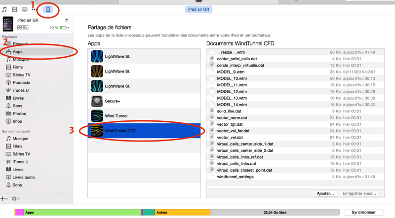
4) Click “Add”, then choose your “.listP” file. It should automatically transfer it to your device and appear in the documents list.
5) On your iPod/iPad, open the Wind Tunnel CFD app, then “File”—>”Open
5) On your iPod/iPad, open the Wind Tunnel CFD app, then “File”—>”Open
It is possible to import external geometry into Wind Tunnel CFD via a custom text file containing the geometry coordinates.
Please find below a description of the text file format to import your own geometry. It consists of physical parameter settings and of a list of geometry coordinates.
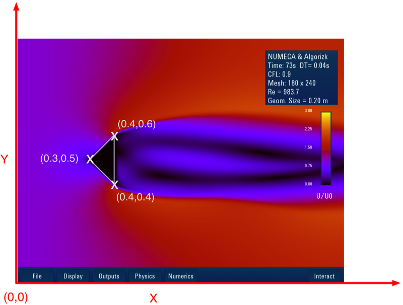
Here is a simple file example defining a triangle ( available also here for download).
#U[m/s] angle[°] D[m] nu[Kg/s/m] CFL[-] Height_of_the_domain [m] (float)
0.1
0.0
0.0
0.00002
0.9
1.0
#Periodic top/bottom (on/off)
0
#Artificial vorticity amplification (on/off)
0
#Geometry
0.4 0.4 0
0.4 0.6 1
0.3 0.5 1
0.4 0.4 1
Lines beginning with a # are comments and not used. The first 6 lines contain the following parameters :
- Input speed in m/s ( 0.1 in this example)
- input angle in ° ( 0.0 in this example)
- characteristic length of the geometry in m, used for reynolds computation (put 0.0 for automatic mode, size will be computed as the hydraulic diameter)
- viscosity in kg/(m.s)
- CFL parameter (typically 0.9)
- Height of the domain in m (typically 1 m)
The next two lines is a boolean (0 or 1 ) to activate periodic boundary contitions from bottom to top.
#Periodic top/bottom (on/off)
0
The next two lines is a boolean (0 or 1 ) to switch on or off the artificial vorticity amplification
#Artificial vorticity amplification (on/off)
0
The last part contains the geometry coordinates :
#Geometry
0.4 0.4 0
0.4 0.6 1
0.3 0.5 1
0.4 0.4 1
Each line contains 3 values :
- the x coordinate, the y coordinate and a boolean telling when a new line is beginning (0 for begin of new line)
The simulation will connect the points with line segments.
Please find below a description of the text file format to import your own geometry. It consists of physical parameter settings and of a list of geometry coordinates.
Here is a simple file example defining a triangle ( available also here for download).
#U[m/s] angle[°] D[m] nu[Kg/s/m] CFL[-] Height_of_the_domain [m] (float)
0.1
0.0
0.0
0.00002
0.9
1.0
#Periodic top/bottom (on/off)
0
#Artificial vorticity amplification (on/off)
0
#Geometry
0.4 0.4 0
0.4 0.6 1
0.3 0.5 1
0.4 0.4 1
Lines beginning with a # are comments and not used. The first 6 lines contain the following parameters :
- Input speed in m/s ( 0.1 in this example)
- input angle in ° ( 0.0 in this example)
- characteristic length of the geometry in m, used for reynolds computation (put 0.0 for automatic mode, size will be computed as the hydraulic diameter)
- viscosity in kg/(m.s)
- CFL parameter (typically 0.9)
- Height of the domain in m (typically 1 m)
The next two lines is a boolean (0 or 1 ) to activate periodic boundary contitions from bottom to top.
#Periodic top/bottom (on/off)
0
The next two lines is a boolean (0 or 1 ) to switch on or off the artificial vorticity amplification
#Artificial vorticity amplification (on/off)
0
The last part contains the geometry coordinates :
#Geometry
0.4 0.4 0
0.4 0.6 1
0.3 0.5 1
0.4 0.4 1
Each line contains 3 values :
- the x coordinate, the y coordinate and a boolean telling when a new line is beginning (0 for begin of new line)
The simulation will connect the points with line segments.